analog to digital converterppt Circuit Diagram In electronics, an analog-to-digital converter (ADC, A/D, or A-to-D) is a system that converts an analog signal, such as a sound picked up by a microphone or [Daniel Garcia] sent us a quick tutorial he put together demonstrating how to use an ATmega168 to perform analog to digital conversions. This timely tutorial would make for a nice complimentary pro… Analog pins in Arduino: Arduino has 6 analog channels for reading analog signals of 0 to 5 Volts. Each channel has a separate analog pin. ATmega328P microcontroller has an inbuilt Analog Digital converter with 10-bit resolution. Analog pins in Arduino only can read the analog input. It cannot reproduce the analog voltage.

In electronic hardware design, an Analog-to-Digital Converter (ADC) is essential for converting continuous analog signals into discrete digital numbers, enabling digital systems to process analog input signals. Simple all-in-one app. Recall and act upon what matters. Designed with privacy in mind. OMI NECKLACE: DEV KIT Order your Omi Dev
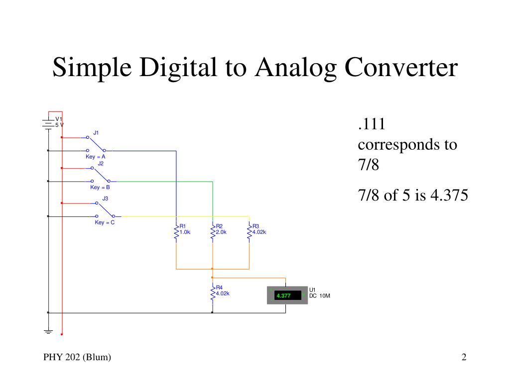
How to Design and Implement an Analog Circuit Diagram
Learn how to make a successive approximation (SAR) Analog to Digital Converter (ADC) that's relatively fast…well, as fast as you want to make it. Using some

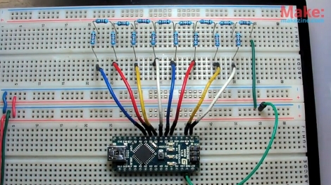
This is a simple type of ADC you can create at home with fairly common parts. I know I skipped over some details like some component values and specific conc
How Analog to Digital Converters Work Circuit Diagram
Digital Signal: A digital signal is a signal that represents data as a sequence of discrete values; at any given time it can only take on one of a finite number of values. Analog Signal: An analog signal is any continuous signal for which the time varying feature of the signal is a representation of some other time-varying quantity i.e., analogous to another time varying signal. The DAC is a digital to analog converter, Vin is the analog input pin, S/H is the sample and hold, and COMP is the comparator. The conversion process is initiated by an analog signal entering the ADC at Vin. Upon receiving the signal, the control unit of the ADC will give a command to the successive approximation register, which starts