
Design of motor control systems as a multi Circuit Diagram AC induction motors have simple and inexpensive control electronics, making them easy to implement in motor control systems. The use of a feedback device is optional, providing flexibility in design.
Motor control circuits are electrical systems that allow you to control the speed and direction of motors. These circuits are used in a variety of industrial, medical, and recreational applications, from robotic arms to automated door openers.
Guide to Basic Electric Motor Control System Design Circuit Diagram
Electric motor control is a crucial aspect of numerous industrial, commercial, and residential applications. By understanding the basics of motor control system design, you can optimize the performance, energy efficiency, and safety of motor-driven systems. Motor control circuits are often connected to lower voltages than the motor they control to make it safer for operators and maintenance personnel.

Explore various electric motor control circuit diagrams, including single-phase and three-phase motor control circuits, to understand how they work and how to design them for different applications. Learn about different control methods, such as direct on-line, star-delta, and VFD control, and discover common components used in motor control circuits. Basics of Motors + Motor Control - what are they, and what do we want to do? A motor is an electro-mechanical device that takes electrical energy and converts it to mechanical energy, and vice-versa. Motors are super cool! They spin! And understanding how a motor works is critical for certain systems, especially if you want to design a motor controller. The lecture video itself contains a more Conclusion Understanding the different types of motor control circuits is crucial for ensuring efficient and reliable operation of electric motors. By selecting the appropriate circuit and implementing proper wiring practices, you can optimize system performance and minimize downtime.
An illustrated guide to motor control circuit diagrams
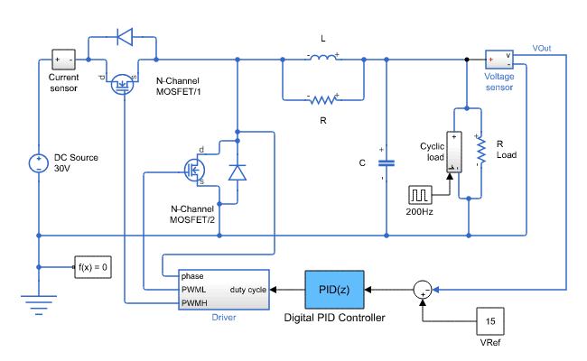
The next figure below shows a very simple DC motor speed controller circuit that employs a MOSFET as a high-power potentiometer (rheostat). The circuit is designed to work with 12 volt DC motors having a peak current usage of below 5 amp.
