
Simple Electronic Fuse Circuit Homemade Circuit Projects 60 OFF Circuit Diagram This rather defeats the purpose of a very fast electronic fuse. Some circuits are more amenable to applying a delay than others. It's easy with the Figure 5.1.1 circuit (see Figure 5.1.2), but harder (and less predictable) with the circuits shown in Figures 5.1.3, 5.1.4 and 5.1.5. including but not limited to all text and diagrams, is the
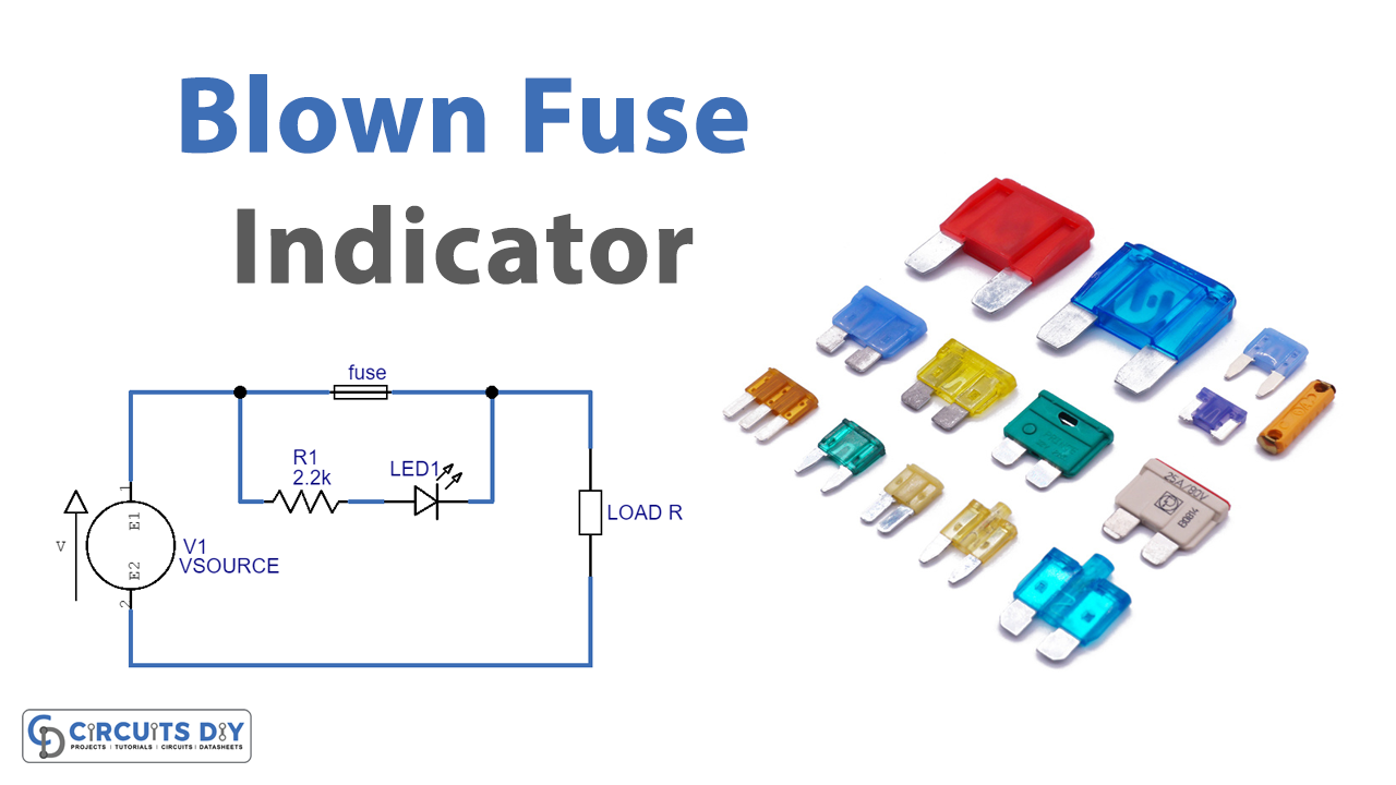
A basic electronic fuse circuit diagram is composed of symbols representing the components of the circuit, including the switch, the fuse, the capacitors, the inductors and the resistors. The purpose of each component is also represented by its own symbol. As such, understanding the symbols used in the diagrams is essential for readers to

Simple electronic fuse circuit Circuit Diagram
Electronic Fuse Schematic Diagram . Current fuse can be set to the maximum output current (about 10 mA) up to the maximum allowable current of the transistor T1 (BUZ11 - 20A). the fuse is power supply of +5 V with integrated stabilizer 7805, +5 V voltage reference voltage and therefore stability is important to determine the accuracy of the

Electronic DC fuse circuit diagram. The current flowing through the thyristor T1 will sink below the holding level when the current is rerouted through the transistor T2 2N3055. T2 and RS are built into the electronic fuse circuit for this purpose. If the voltage drop at RS exceeds above base-emitter-diode trigger voltage of the T2, the
PDF Basics of eFuses (Rev. A) Circuit Diagram
Fuses, positive temperature coefficient (PTC) resistors, and active circuit protection are a few of the protection devices with varied capabilities and drawbacks. Fuses are traditionally considered as protection devices used to isolate overload or short-circuit faults from the main system. Although these devices
